Senseair S8 CO2 Sensor Modbus RTU Debugging Guide
In this case study, we successfully establish communication with a Senseair S8 Commercial NDIR CO2 sensor over Modbus RTU using a 3.3V UART TTL connection. By leveraging CycBox's serial transport and Modbus RTU codec, we unpack the exact device initialization sequence, validate the continuous measurement polling loop, and decode the CO2 ppm readings alongside critical system diagnostic flags.
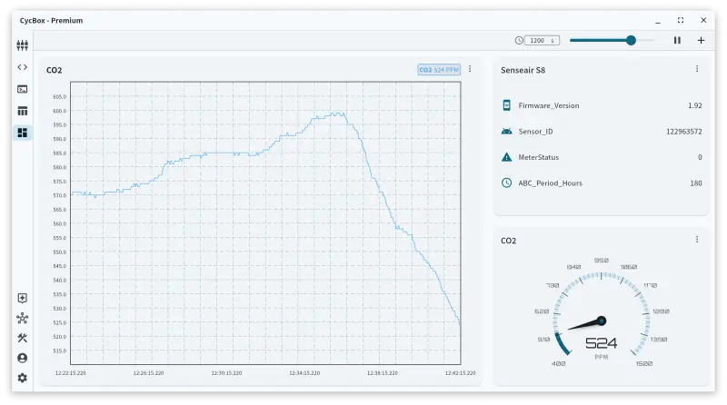
Device under test
- Model / manufacturer / category: Senseair S8 Commercial (Article No. 004-0-0010, 004-0-0075) / Senseair / NDIR CO2 Sensor
- Role in the system: Measures ambient carbon dioxide concentrations for HVAC control, indoor air quality monitoring, and safety systems.
- Electrical interface: UART 3.3V CMOS logic (requires external RS-485 transceiver if used on a long bus).
- Power requirements: Supply voltage (VCC/G+) of 4.5V – 5.25V. The sensor draws a 30 mA average but requires handling for a 300 mA peak current during the measurement lamp cycle.
- Key datasheet specs:
- Measurement range: 400 – 2000 ppm (standard accuracy), reports up to 10000 ppm (extended).
- Accuracy: ±30 ppm ±3% of reading.
- Measurement interval: 2 seconds.
- Automatic Baseline Correction (ABC): 8 days default.
- Source documents: PSP103.pdf (Hardware Specification), TDE2067.pdf (Modbus Protocol Reference).
Wire protocol and CycBox stack
The Senseair S8 operates strictly as a Modbus RTU slave over a serial connection.
- Transport:
serial_port_transportconfigured for/dev/ttyACM0at 9600 baud, 8 data bits, no parity, and 1 stop bit. Note: The datasheet specifies the sensor receives with 1 stop bit but transmits with 2. In practice, configuring the CycBox (or a host MCU) for 1 stop bit works flawlessly because the extra stop bit sent by the sensor simply blends into the inter-frame idle time. - Codec:
modbus_rtu_codecwith a 20 ms receive timeout.
Protocol deep-dive: Modbus RTU on the Senseair S8
The sensor implements a subset of Modbus RTU with strict payload constraints. It supports reading holding registers (
0x03), reading input registers (0x04), and writing single holding registers (0x06). Crucially, the maximum packet
length the sensor will process is 39 bytes (including the address and CRC). Any frame exceeding this length is silently
discarded.
While individual sensors have a specific node address (1–247), address 254 (0xFE) acts as the "Any Sensor" broadcast
address. This is incredibly useful for point-to-point debugging or initializing a sensor before its factory address is
known.
The table below maps the vital Senseair S8 Modbus registers to their functions, types, and scaling factors.
| Address (Hex) | Modbus Type | Field Name | Description | Scale / Unit |
|---|---|---|---|---|
0x0000 | Input Reg (04) | MeterStatus | System fault and error bitfield | Bitfield (0x0000 = OK) |
0x0002 | Input Reg (04) | Output Status | Discrete alarm and PWM states | Bitfield |
0x0003 | Input Reg (04) | Space CO2 | Active carbon dioxide measurement | 1 ppm |
0x001B | Input Reg (04) | Map Version | Firmware memory map version | Raw integer |
0x001C | Input Reg (04) | Firmware Version | Main.Sub version (High/Low bytes) | High=Main, Low=Sub |
0x001D | Input Reg (04) | Sensor ID High | Upper 16 bits of serial number | Raw integer |
0x001E | Input Reg (04) | Sensor ID Low | Lower 16 bits of serial number | Raw integer |
0x0000 | Holding Reg (03) | Acknowledgement | Calibration execution flags | Bitfield |
0x0001 | Holding Reg (03) | Special Command | Trigger background/zero calibration | 0x7C06 = Background |
0x001F | Holding Reg (03) | ABC Period | Auto Baseline Correction interval | Hours (0 = Disabled) |
CycBox configuration walkthrough
Transport & codec config
[
  {
    "app": {
      "app_transport": "serial_port_transport",
      "app_codec": "modbus_rtu_codec",
      "app_transformer": "disable_transformer",
      "app_encoding": "UTF-8"
    },
    "serial_port_transport": {
      "serial_port_transport_parity": "none",
      "serial_port_transport_port": "/dev/ttyACM0",
      "serial_port_transport_stop_bits": "1",
      "serial_port_transport_flow_control": "none",
      "serial_port_transport_baud_rate": 9600,
      "serial_port_transport_data_bits": 8
    },
    "modbus_rtu_codec": {
      "with_receive_timeout": 20
    }
  }
]
Lua script
The following Lua script orchestrates the Modbus flow. On startup, it queries the static device identity and the ABC calibration period. It then kicks off a recurring 2-second timer to fetch the active CO2 measurements and system health status.
local SLAVE_ADDR = 254
local POLL_MS = 2000
local timer_ms = 0

function on_start()
    log("info", "Starting Senseair S8 Modbus polling script.")

    -- Poll device information and configuration once at startup
    -- Read 4 registers starting at 0x001B: Map Ver, FW Ver, Sensor ID Hi, Sensor ID Lo
    modbus_rtu_read_input_registers(SLAVE_ADDR, 0x001B, 4, 100, 0)
    -- Read 1 holding register at 0x001F: ABC Period
    modbus_rtu_read_holding_registers(SLAVE_ADDR, 0x001F, 1, 200, 0)
end

function on_timer(now_ms)
    timer_ms = timer_ms + 100

    -- Periodically read active data (CO2, status, alarms) every 2 seconds
    if timer_ms >= POLL_MS then
        -- Read 4 registers starting at 0x0000: MeterStatus, AlarmStatus, OutputStatus, SpaceCO2
        modbus_rtu_read_input_registers(SLAVE_ADDR, 0x0000, 4, 0, 0)
        timer_ms = 0
    end
end

function on_receive()
    if message.connection_id ~= 0 then return false end
    local modified = false

    -- Parse Space CO2 (Protocol address 0x0003)
    local co2 = message:get_value(string.format("modbus_rtu_%d:input_0003", SLAVE_ADDR))
    if co2 then
        message:add_int_value("CO2_ppm", co2)
        modified = true
    end

    -- Parse MeterStatus (Protocol address 0x0000)
    local status = message:get_value(string.format("modbus_rtu_%d:input_0000", SLAVE_ADDR))
    if status then
        message:add_int_value("MeterStatus", status)
        if status ~= 0 then
            local fatal = bit.band(status, 0x01)
            local out_of_range = bit.band(status, 0x20)
            if fatal > 0 then log("error", "Sensor reported FATAL ERROR (bit 0)") end
            if out_of_range > 0 then log("warn", "Sensor reading OUT OF RANGE (bit 5)") end
        end
        modified = true
    end

    -- Parse OutputStatus / Alarms (Protocol address 0x0002)
    local out_status = message:get_value(string.format("modbus_rtu_%d:input_0002", SLAVE_ADDR))
    if out_status then
        -- Alarm state is inverted natively but output bit 0 reflects discrete alarm
        local alarm = (bit.band(out_status, 0x01) > 0)
        message:add_bool_value("Alarm_Active", alarm)
        modified = true
    end

    -- Parse Firmware Version (Protocol address 0x001C)
    local fw = message:get_value(string.format("modbus_rtu_%d:input_001C", SLAVE_ADDR))
    if fw then
        local main_ver = bit.rshift(fw, 8)
        local sub_ver = bit.band(fw, 0xFF)
        message:add_string_value("Firmware_Version", string.format("%d.%d", main_ver, sub_ver))
        modified = true
    end

    -- Parse Sensor ID (Combined Protocol addresses 0x001D and 0x001E)
    local id_hi = message:get_value(string.format("modbus_rtu_%d:input_001D", SLAVE_ADDR))
    local id_lo = message:get_value(string.format("modbus_rtu_%d:input_001E", SLAVE_ADDR))
    if id_hi and id_lo then
        local sensor_id = id_hi * 65536 + id_lo
        message:add_int_value("Sensor_ID", sensor_id)
        modified = true
    end

    -- Parse ABC Period (Protocol address 0x001F)
    local abc = message:get_value(string.format("modbus_rtu_%d:holding_001F", SLAVE_ADDR))
    if abc then
        message:add_int_value("ABC_Period_Hours", abc)
        modified = true
    end

    return modified
end
Debugging journey
Step 1 — Verify device identity and firmware via broadcast address
- Goal: Confirm the physical layer is functional and read the sensor's firmware version. Since the specific slave ID
was unknown, we utilized the universal address
0xFE(254). - What we did: Sent a Read Input Registers (
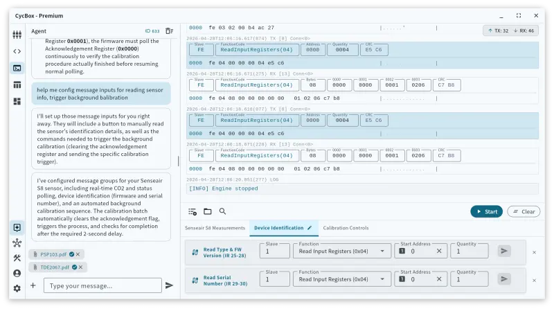
0x04) request to0x001Bwith a quantity of 4 registers to capture the map version, firmware version, and 32-bit sensor ID. - What the device returned:
TX: fe 04 00 1b 00 04 95 c1
RX: fe 04 08 00 31 01 5c 07 54 46 74 94 e6 - Diagnosis: Success. The payload (
00 31 01 5C 07 54 46 74) decoded cleanly. The firmware version register (0x001C) contained0x015C, which parsed to1.92(Main0x01, Sub0x5C). The Sensor ID (0x0754concatenated with0x4674) equated to decimal122963572.
Step 2 — Read Automatic Baseline Correction (ABC) period
- Goal: Validate the factory baseline calibration setting.
- What we did: Requested a Read Holding Registers (
0x03) to0x001Ffor 1 register. - What the device returned:
TX: fe 03 00 1f 00 01 a1 c3
RX: fe 03 02 00 b4 ac 27 - Diagnosis: The returned payload
0x00B4equals 180 in decimal. Since the unit is hours, 180 hours translates to exactly 7.5 days, verifying that the ABC functionality is active and correctly configured.
Step 3 — Execute the 2-second telemetry polling loop
- Goal: Continuously read the active CO2 ppm reading and the system status flags.
- What we did: Requested a Read Input Registers (
0x04) to0x0000with a quantity of 4 to fetchMeterStatus,AlarmStatus,OutputStatus, andSpace CO2in a single transaction. - What the device returned:
TX: fe 04 00 00 00 04 e5 c6
RX: fe 04 08 00 00 00 00 00 01 02 06 c7 b8 - Diagnosis: Perfect execution.
- Bytes 0-1 (
00 00):MeterStatusis0, indicating zero internal faults. - Bytes 4-5 (
00 01):OutputStatushas bit 0 high, indicating normal operation. - Bytes 6-7 (
02 06):Space CO2equals 518 decimal. The sensor was reading an ambient 518 ppm CO2 environment. This sequence repeated predictably every 2 seconds.
- Bytes 0-1 (
Observed behaviour and validation
- Timing constraints: The 2-second polling interval strictly adhered to the datasheet's measurement cycle. Polling faster does not yield new CO2 data and occupies unnecessary bus time. The sensor responded consistently within 40 ms to all valid queries.
- Broadcast addressing: Using
0xFEallows communication without knowing the factory slave address. Note that if multiple Senseair S8 sensors are on the same RS-485 bus, querying0xFEwill cause packet collisions as all sensors answer simultaneously. - Voltage disparity: While the serial lines operate at 3.3V CMOS logic, the power supply must be an unregulated 5V source capable of absorbing brief 300 mA spikes.
Porting to MCU firmware (design reference, no code)
To build a production-grade driver for the Senseair S8, firmware engineers should design around the following guidelines.
- Suggested MCU class: STM32G0/F4, ESP32, or NXP i.MX RT. The MCU needs one UART peripheral and a timer for the polling loop.
The table below details the specific MCU peripheral settings required for the serial interface.
| Peripheral Parameter | Required Setting | Notes |
|---|---|---|
| Baud Rate | 9600 bps | Fixed by factory, non-negotiable. |
| Data Bits | 8 | Standard Modbus RTU. |
| Parity | None | Standard Modbus RTU. |
| Stop Bits | 1 | Sensor transmits 2, MCU can safely use 1. |
| Logic Level | 3.3V TTL | 5V tolerant pins recommended, but not mandatory. |
| DE / RE Control | GPIO toggle | Required only if driving an external RS-485 transceiver. |
Device initialization sequence
- Power-On Delay: Wait at least 2 seconds after applying 5V power before sending the first frame to allow the sensor to boot and conduct its internal self-diagnostics.
- Identification Sync: Issue a
Read Input Registers (0x04)request to address0x001Bto retrieve the firmware version and establish bus sanity. Use node ID0xFEif the assigned ID is unknown. - Verify ABC Configuration: Issue a
Read Holding Registers (0x03)to0x001F. If the application involves an environment that never reaches 400 ppm (like a greenhouse), disable ABC by writing0x0000to this register. - Transition to Polling: Enter the operational state machine.
Message transmission and framing
When assembling the Modbus frame for reading CO2, the firmware must generate the following exact byte sequence for a
Read Input Registers command targeting address 0xFE:
- Offset 0 (Slave ID):
0xFE - Offset 1 (Function):
0x04 - Offset 2-3 (Start Address):
0x00,0x00 - Offset 4-5 (Quantity):
0x00,0x04 - Offset 6-7 (CRC):
0xE5,0xC6(Calculated using CRC16-IBM, polynomial0xA001, transmitted LSB first).
Inter-frame silence: Ensure a minimum delay of 3.5 character times (roughly 4 ms at 9600 baud) before transmitting a new frame to reset the sensor's Modbus state machine.
Error handling and state machine
The table below outlines a simple application state machine to handle the 2-second CO2 polling lifecycle and exceptions.
| State | Event / Trigger | Next State / Action |
|---|---|---|
| INIT | Power applied | Wait 2000 ms, move to IDENTIFY |
| IDENTIFY | FW read successful | Move to POLL_READY |
| POLL_READY | 2000 ms timer expires | Send Read Input Regs (0-3), move to WAIT_RX |
| WAIT_RX | Valid Modbus frame received | Parse MeterStatus. If OK, decode CO2 ppm. Move to POLL_READY |
| WAIT_RX | Rx timeout (> 180 ms) | Increment failure counter. Move to POLL_READY |
| WAIT_RX | MeterStatus bit 0 (Fatal) is 1 | Alarm system. Require physical power cycle. |
| WAIT_RX | MeterStatus bit 5 (OOR) is 1 | Flag "Out of Range" to telemetry. Measurement is invalid. |
Frequently asked questions
What Modbus address does the Senseair S8 use by default?
Out of the box, the specific address can vary, but the sensor always responds to the broadcast address 254 (0xFE).
You can use this to communicate with it immediately, provided it is the only device on the UART/RS-485 line.
Why does the sensor silently ignore my Modbus read request?
The Senseair S8 has a strict 39-byte maximum buffer limit. If you attempt to read too many registers in a single transaction (for example, attempting to read 20 holding registers at once), the required response frame will exceed 39 bytes, and the sensor will drop the request entirely rather than issuing an exception. Limit your reads to quantities of 8 registers or fewer.
How do I check if the sensor is in an error state?
Read Input Register 0x0000 (MeterStatus). A value of 0x0000 means the sensor is healthy. If the value is non-zero,
check the specific bits: Bit 0 indicates a fatal error requiring a restart, while Bit 5 indicates the CO2 reading is out
of range.
Why is my CO2 reading slowly drifting upward over several weeks?
If the sensor never encounters fresh outdoor air (400 ppm), the Automatic Baseline Correction (ABC) algorithm will
incorrectly recalibrate the baseline, causing the readings to skew. If your environment is constantly occupied or
artificially enriched, you must disable ABC by writing 0 to Holding Register 0x001F.
Gotchas and recommendations
- Stop bit mismatch: The datasheet specifies 1 stop bit for receiving and 2 for transmitting. If your MCU UART
cannot handle asymmetrical stop bits, setting your peripheral to
8-N-1is perfectly safe. The extra stop bit sent by the sensor merely acts as idle bus time. - Power supply current spikes: The NDIR lamp draws 300 mA every 2 seconds. If you power the sensor from an MCU's 5V pin that cannot supply this surge, the MCU may brown out. Ensure adequate bulk capacitance near the sensor's VCC pin.
- Write constraints: The sensor only supports Modbus Function
0x06(Write Single Register). It does not support0x10(Write Multiple Registers). Firmware must write configuration values one register at a time. - Field Calibration: If manual background calibration is performed (writing to Holding Register
0x0001), the firmware must poll the Acknowledgement Register (0x0000) continuously to verify the calibration procedure actually finished before resuming normal polling.